
Kitchen wall cabinets
Single upward-opening fronts with side-mounted brackets.
Match the support behind an upward-opening cabinet flap by its part marking, mounting length, force and brackets. Compare published references, then send the parts and quantities you need.
Matching product family: Compression gas springs →
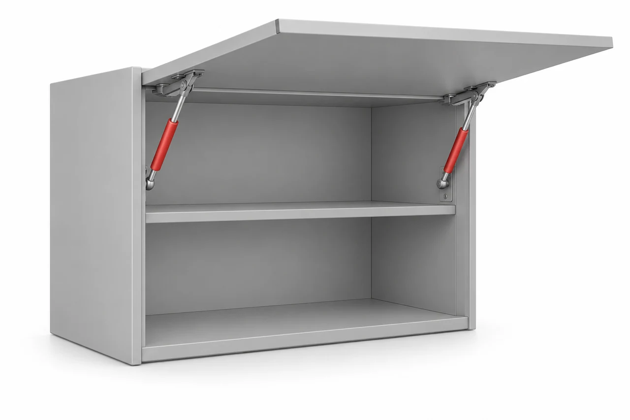
Assisted opening and support at the open position. A soft-stop design controls the end of travel; it does not automatically mean a lockable spring.
Single upward-opening fronts with side-mounted brackets.
Furniture and storage-unit flaps where access is from below.
Lift-up, drop-down and folding fronts use different mechanisms. Identify the action before choosing a spring or damper.
Use the original marking or a drawing wherever possible. Measurements may be supplied in millimeters or inches.
Complete code and force printed on the cylinder, with a clear photograph.
Fully extended mounting-centre length, compressed length if documented, and travel.
Flap height, width, weight, opening angle and the location of both brackets.
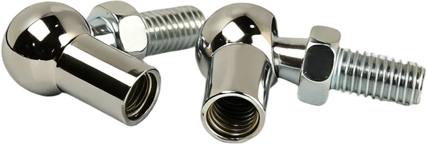
Ball or pin size, socket or eye geometry, springs per flap and order quantity.
The published cabinet examples use their own flap material, weight, spring quantity and mounting geometry. A force value alone is not a universal door-weight rating.
Choose a reference and include your quantity. Each record keeps its original dimensional scope and a link to the source.
Published application references help identify your request. They are not Horizon stock codes. Confirm the exact assembly, fittings and quantity in your quotation. Unpublished specifications are left open for matching.
For the source mounting arrangement and 18 mm MDF/chipboard; listed flap sizes, weight and spring quantity are one conditional example.
Drawing length L: 244 ±2 mm / 9.61 in (nominal)
Max. stroke: 85 mm / 3.35 in
Force: 50 N / ≈11.2 lbf
Extended mounting-centre length as drawn on the source page
C9 rod-side attachment S06210024; C7 tube-side attachment S06210025 with pin S06210026
Source example: 18 mm MDF/chipboard; 600 mm wide; 351–400 mm high; 2.5–2.8 kg; 2 spring(s). Use the source mounting geometry.
For the source mounting arrangement and 18 mm MDF/chipboard; listed flap sizes, weight and spring quantity are one conditional example.
Drawing length L: 244 ±2 mm / 9.61 in (nominal)
Max. stroke: 85 mm / 3.35 in
Force: 80 N / ≈18.0 lbf
Extended mounting-centre length as drawn on the source page
C9 rod-side attachment S06210024; C7 tube-side attachment S06210025 with pin S06210026
Source example: 18 mm MDF/chipboard; 450 mm wide; 300–350 mm high; 1.6–1.8 kg; 1 spring(s). Use the source mounting geometry.
For the source mounting arrangement and 18 mm MDF/chipboard; listed flap sizes, weight and spring quantity are one conditional example.
Drawing length L: 244 ±2 mm / 9.61 in (nominal)
Max. stroke: 85 mm / 3.35 in
Force: 100 N / ≈22.5 lbf
Extended mounting-centre length as drawn on the source page
C9 rod-side attachment S06210024; C7 tube-side attachment S06210025 with pin S06210026
Source example: 18 mm MDF/chipboard; 600 mm wide; 501–550 mm high; 3.5–3.9 kg; 2 spring(s). Use the source mounting geometry.
For the source mounting arrangement and 18 mm MDF/chipboard; listed flap sizes, weight and spring quantity are one conditional example.
Drawing length L: 244 ±2 mm / 9.61 in (nominal)
Max. stroke: 85 mm / 3.35 in
Force: 120 N / ≈27.0 lbf
Extended mounting-centre length as drawn on the source page
C9 rod-side attachment S06210024; C7 tube-side attachment S06210025 with pin S06210026
Source example: 18 mm MDF/chipboard; 600 mm wide; 551–600 mm high; 3.9–4.2 kg; 2 spring(s). Use the source mounting geometry.
For the source mounting arrangement and 18 mm MDF/chipboard; listed flap sizes, weight and spring quantity are one conditional example.
Drawing length L: 244 ±2 mm / 9.61 in (nominal)
Max. stroke: 85 mm / 3.35 in
Force: 50 N / ≈11.2 lbf
Extended mounting-centre length as drawn on the source page
C9 rod-side attachment S06210024; C7 tube-side attachment S06210025 with pin S06210026
Source example: 18 mm MDF/chipboard; 600 mm wide; 351–400 mm high; 2.5–2.8 kg; 2 spring(s). Use the source mounting geometry.
For the source mounting arrangement and 18 mm MDF/chipboard; listed flap sizes, weight and spring quantity are one conditional example.
Drawing length L: 244 ±2 mm / 9.61 in (nominal)
Max. stroke: 85 mm / 3.35 in
Force: 80 N / ≈18.0 lbf
Extended mounting-centre length as drawn on the source page
C9 rod-side attachment S06210024; C7 tube-side attachment S06210025 with pin S06210026
Source example: 18 mm MDF/chipboard; 450 mm wide; 300–350 mm high; 1.6–1.8 kg; 1 spring(s). Use the source mounting geometry.
For the source mounting arrangement and 18 mm MDF/chipboard; listed flap sizes, weight and spring quantity are one conditional example.
Drawing length L: 244 ±2 mm / 9.61 in (nominal)
Max. stroke: 85 mm / 3.35 in
Force: 100 N / ≈22.5 lbf
Extended mounting-centre length as drawn on the source page
C9 rod-side attachment S06210024; C7 tube-side attachment S06210025 with pin S06210026
Source example: 18 mm MDF/chipboard; 600 mm wide; 501–550 mm high; 3.5–3.9 kg; 2 spring(s). Use the source mounting geometry.
For the source mounting arrangement and 18 mm MDF/chipboard; listed flap sizes, weight and spring quantity are one conditional example.
Drawing length L: 244 ±2 mm / 9.61 in (nominal)
Max. stroke: 85 mm / 3.35 in
Force: 120 N / ≈27.0 lbf
Extended mounting-centre length as drawn on the source page
C9 rod-side attachment S06210024; C7 tube-side attachment S06210025 with pin S06210026
Source example: 18 mm MDF/chipboard; 600 mm wide; 551–600 mm high; 3.9–4.2 kg; 2 spring(s). Use the source mounting geometry.
For the source mounting arrangement and 18 mm MDF/chipboard; listed flap sizes, weight and spring quantity are one conditional example.
Drawing length L: 244 ±2 mm / 9.61 in (nominal)
Max. stroke: 85 mm / 3.35 in
Force: 45 N / ≈10.1 lbf
Extended mounting-centre length as drawn on the source page
C9 rod-side attachment S06210024; C7 tube-side attachment S06210025 with pin S06210026
Source example: 18 mm MDF/chipboard; 450 mm wide; 300–350 mm high; 1.6–1.8 kg; 1 spring(s). Use the source mounting geometry.
For the source mounting arrangement and 18 mm MDF/chipboard; listed flap sizes, weight and spring quantity are one conditional example.
Drawing length L: 244 ±2 mm / 9.61 in (nominal)
Max. stroke: 85 mm / 3.35 in
Force: 60 N / ≈13.5 lbf
Extended mounting-centre length as drawn on the source page
C9 rod-side attachment S06210024; C7 tube-side attachment S06210025 with pin S06210026
Source example: 18 mm MDF/chipboard; 600 mm wide; 300–350 mm high; 2.1–2.5 kg; 1 spring(s). Use the source mounting geometry.
For the source mounting arrangement and 18 mm MDF/chipboard; listed flap sizes, weight and spring quantity are one conditional example.
Drawing length L: 244 ±2 mm / 9.61 in (nominal)
Max. stroke: 85 mm / 3.35 in
Force: 90 N / ≈20.2 lbf
Extended mounting-centre length as drawn on the source page
C9 rod-side attachment S06210024; C7 tube-side attachment S06210025 with pin S06210026
Source example: 18 mm MDF/chipboard; 900 mm wide; 300–350 mm high; 3.2–3.7 kg; 1 spring(s). Use the source mounting geometry.
For the source mounting arrangement and 4 mm glass in metal/aluminium frame; listed flap sizes, weight and spring quantity are one conditional example.
Drawing length L: 245 ±2 mm / 9.65 in (nominal)
Max. stroke: 80 mm / 3.15 in
Force: 50 N / ≈11.2 lbf
Extended mounting-centre length as drawn on the source page
C10 rod-side attachment S06710163; C11 tube-side attachment S06810013; 10 mm ball system
Source example: 4 mm glass in metal/aluminium frame; 600 mm wide; 351–400 mm high; 2.5–2.8 kg; 2 spring(s). Use the source mounting geometry.
For the source mounting arrangement and 4 mm glass in metal/aluminium frame; listed flap sizes, weight and spring quantity are one conditional example.
Drawing length L: 245 ±2 mm / 9.65 in (nominal)
Max. stroke: 80 mm / 3.15 in
Force: 80 N / ≈18.0 lbf
Extended mounting-centre length as drawn on the source page
C10 rod-side attachment S06710163; C11 tube-side attachment S06810013; 10 mm ball system
Source example: 4 mm glass in metal/aluminium frame; 450 mm wide; 300–350 mm high; 1.6–1.8 kg; 1 spring(s). Use the source mounting geometry.
For the source mounting arrangement and 4 mm glass in metal/aluminium frame; listed flap sizes, weight and spring quantity are one conditional example.
Drawing length L: 245 ±2 mm / 9.65 in (nominal)
Max. stroke: 80 mm / 3.15 in
Force: 100 N / ≈22.5 lbf
Extended mounting-centre length as drawn on the source page
C10 rod-side attachment S06710163; C11 tube-side attachment S06810013; 10 mm ball system
Source example: 4 mm glass in metal/aluminium frame; 600 mm wide; 501–550 mm high; 3.5–3.9 kg; 2 spring(s). Use the source mounting geometry.
For the source mounting arrangement and 4 mm glass in metal/aluminium frame; listed flap sizes, weight and spring quantity are one conditional example.
Drawing length L: 245 ±2 mm / 9.65 in (nominal)
Max. stroke: 80 mm / 3.15 in
Force: 120 N / ≈27.0 lbf
Extended mounting-centre length as drawn on the source page
C10 rod-side attachment S06710163; C11 tube-side attachment S06810013; 10 mm ball system
Source example: 4 mm glass in metal/aluminium frame; 600 mm wide; 551–600 mm high; 3.9–4.2 kg; 2 spring(s). Use the source mounting geometry.
For the source mounting arrangement and 4 mm glass in metal/aluminium frame; listed flap sizes, weight and spring quantity are one conditional example.
Drawing length L: 245 ±2 mm / 9.65 in (nominal)
Max. stroke: 80 mm / 3.15 in
Force: 50 N / ≈11.2 lbf
Extended mounting-centre length as drawn on the source page
C10 rod-side attachment S06710163; C11 tube-side attachment S06810013; 10 mm ball system
Source example: 4 mm glass in metal/aluminium frame; 600 mm wide; 351–400 mm high; 2.5–2.8 kg; 2 spring(s). Use the source mounting geometry.
For the source mounting arrangement and 4 mm glass in metal/aluminium frame; listed flap sizes, weight and spring quantity are one conditional example.
Drawing length L: 245 ±2 mm / 9.65 in (nominal)
Max. stroke: 80 mm / 3.15 in
Force: 80 N / ≈18.0 lbf
Extended mounting-centre length as drawn on the source page
C10 rod-side attachment S06710163; C11 tube-side attachment S06810013; 10 mm ball system
Source example: 4 mm glass in metal/aluminium frame; 450 mm wide; 300–350 mm high; 1.6–1.8 kg; 1 spring(s). Use the source mounting geometry.
For the source mounting arrangement and 4 mm glass in metal/aluminium frame; listed flap sizes, weight and spring quantity are one conditional example.
Drawing length L: 245 ±2 mm / 9.65 in (nominal)
Max. stroke: 80 mm / 3.15 in
Force: 100 N / ≈22.5 lbf
Extended mounting-centre length as drawn on the source page
C10 rod-side attachment S06710163; C11 tube-side attachment S06810013; 10 mm ball system
Source example: 4 mm glass in metal/aluminium frame; 600 mm wide; 501–550 mm high; 3.5–3.9 kg; 2 spring(s). Use the source mounting geometry.
For the source mounting arrangement and 4 mm glass in metal/aluminium frame; listed flap sizes, weight and spring quantity are one conditional example.
Drawing length L: 245 ±2 mm / 9.65 in (nominal)
Max. stroke: 80 mm / 3.15 in
Force: 120 N / ≈27.0 lbf
Extended mounting-centre length as drawn on the source page
C10 rod-side attachment S06710163; C11 tube-side attachment S06810013; 10 mm ball system
Source example: 4 mm glass in metal/aluminium frame; 600 mm wide; 551–600 mm high; 3.9–4.2 kg; 2 spring(s). Use the source mounting geometry.
For the source mounting arrangement and 4 mm glass in metal/aluminium frame; listed flap sizes, weight and spring quantity are one conditional example.
Drawing length L: 245 ±2 mm / 9.65 in (nominal)
Max. stroke: 80 mm / 3.15 in
Force: 45 N / ≈10.1 lbf
Extended mounting-centre length as drawn on the source page
C10 rod-side attachment S06710163; C11 tube-side attachment S06810013; 10 mm ball system
Source example: 4 mm glass in metal/aluminium frame; 450 mm wide; 300–350 mm high; 1.6–1.8 kg; 1 spring(s). Use the source mounting geometry.
For the source mounting arrangement and 4 mm glass in metal/aluminium frame; listed flap sizes, weight and spring quantity are one conditional example.
Drawing length L: 245 ±2 mm / 9.65 in (nominal)
Max. stroke: 80 mm / 3.15 in
Force: 60 N / ≈13.5 lbf
Extended mounting-centre length as drawn on the source page
C10 rod-side attachment S06710163; C11 tube-side attachment S06810013; 10 mm ball system
Source example: 4 mm glass in metal/aluminium frame; 600 mm wide; 300–350 mm high; 2.1–2.5 kg; 1 spring(s). Use the source mounting geometry.
For the source mounting arrangement and 4 mm glass in metal/aluminium frame; listed flap sizes, weight and spring quantity are one conditional example.
Drawing length L: 245 ±2 mm / 9.65 in (nominal)
Max. stroke: 80 mm / 3.15 in
Force: 90 N / ≈20.2 lbf
Extended mounting-centre length as drawn on the source page
C10 rod-side attachment S06710163; C11 tube-side attachment S06810013; 10 mm ball system
Source example: 4 mm glass in metal/aluminium frame; 900 mm wide; 300–350 mm high; 3.2–3.7 kg; 1 spring(s). Use the source mounting geometry.
No matching reference is listed. Send the complete marking, photos and quantity →
Reference and quantity → matched dimensions, fittings and release arrangement → agreed specification for the quotation and repeat order.
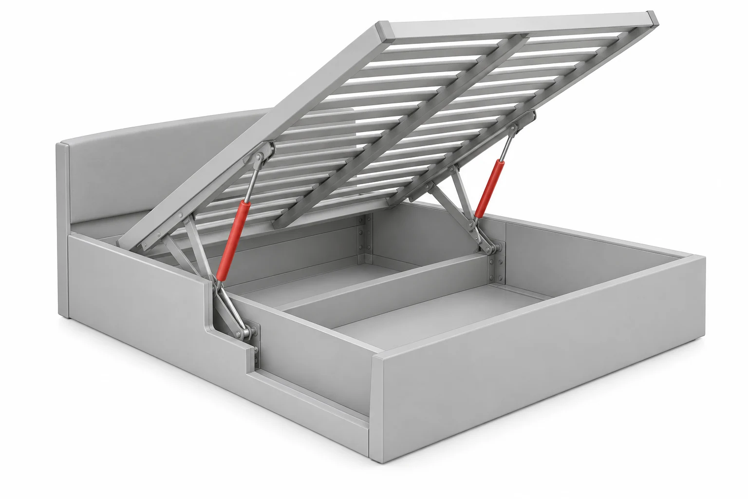
Lift-up bed bases with accessible storage beneath the mattress.
Find the right support ↗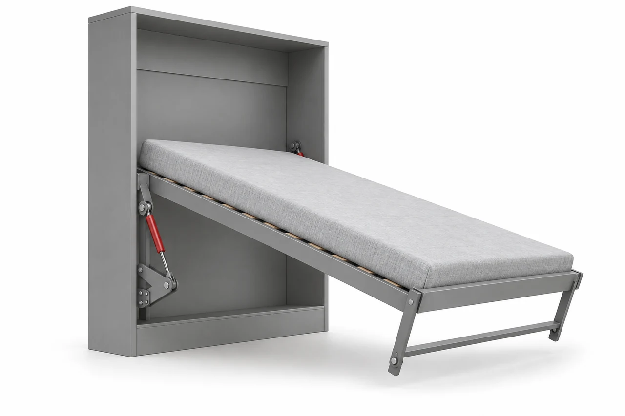
Vertical and horizontal foldaway-bed mechanisms.
Find the right support ↗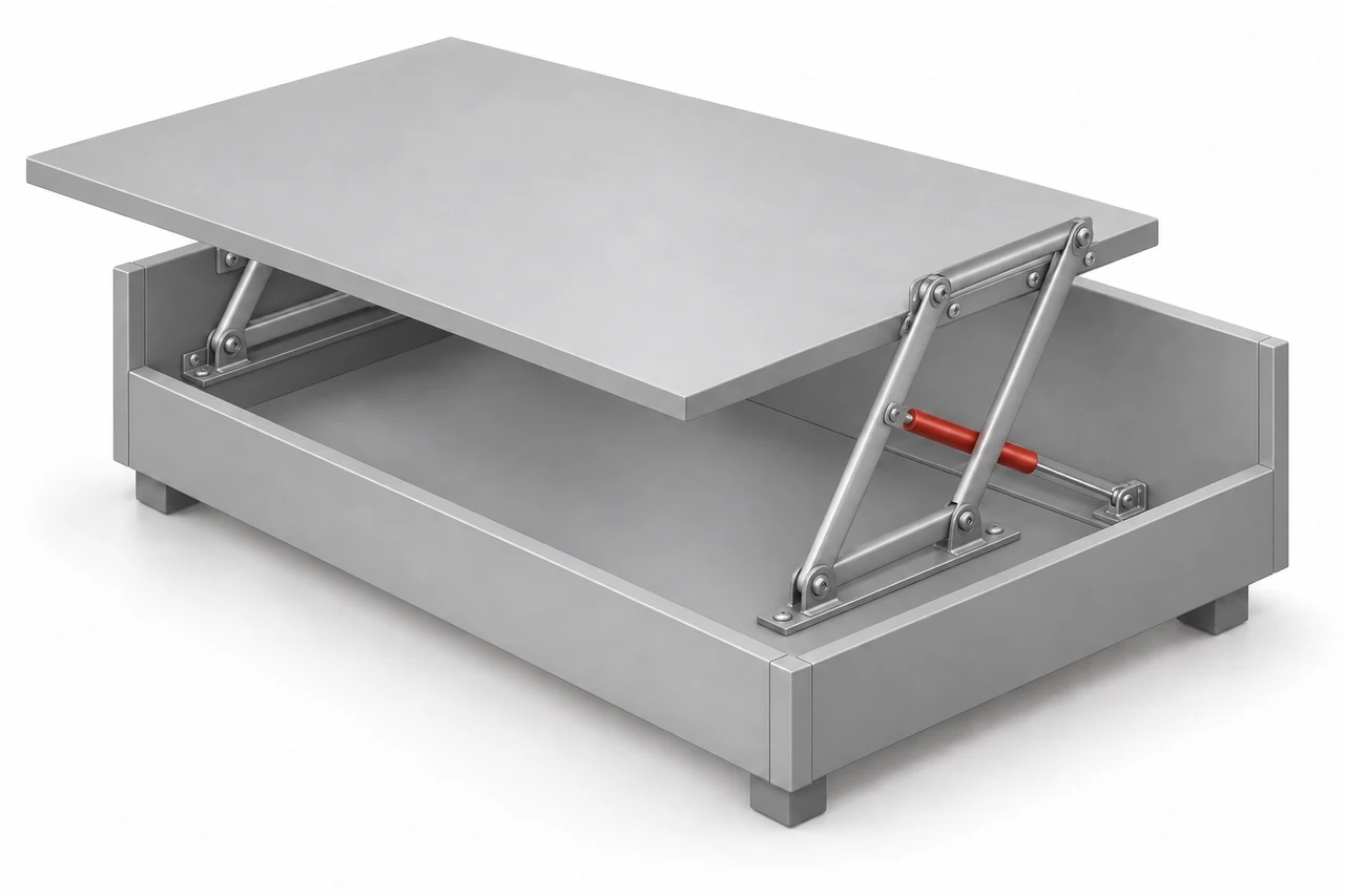
Swing-up coffee-table tops and controlled table-height adjustment.
Find the right support ↗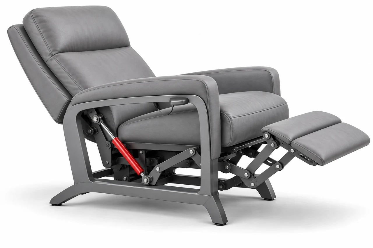
Controlled backrest and armrest adjustment in seating mechanisms.
Find the right support ↗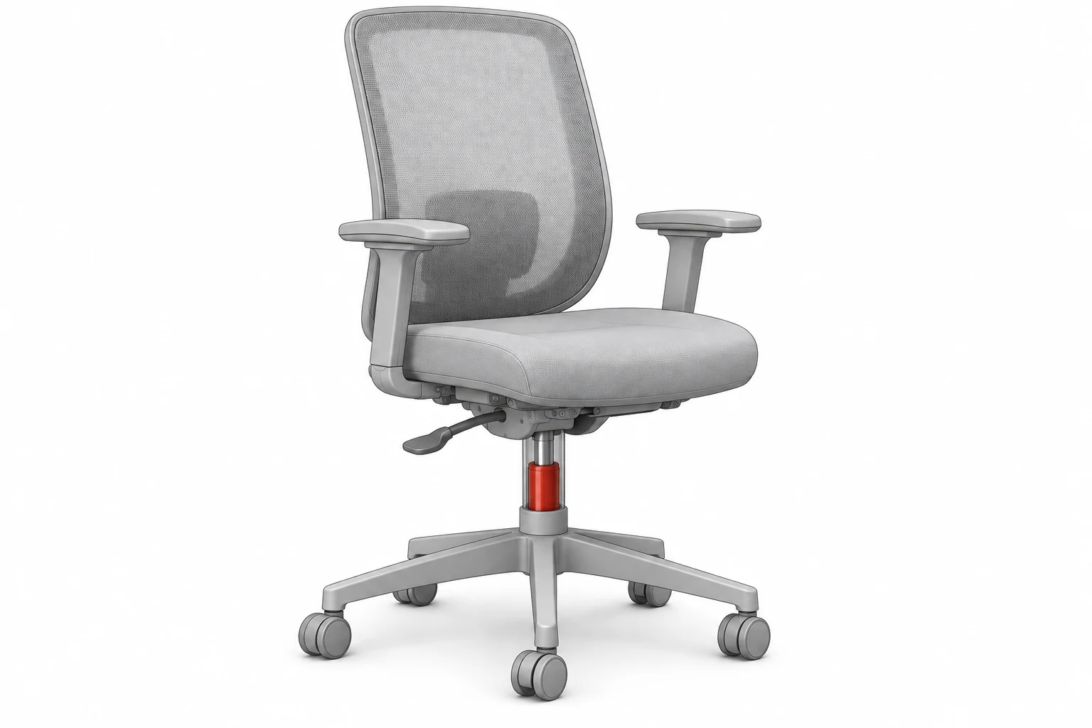
Dedicated seat-height columns and their base/seat interfaces.
Find the right support ↗Application reading: SUSPA furniture applications · Stabilus home furniture applications · Stabilus office furniture applications. Manufacturer examples explain functions; they do not establish Horizon compatibility or certification.