Skip to content
GAS SPRINGS & LIFT SUPPORTS · B2B SUPPLY
sales@horizongasspring.com
Language / EN

Read in your language

Automatic translation by Google. Opens in a new tab.

English Original website

Quotes & PDF catalog: original English website.

PRODUCT RANGE

Lockable Gas Springs

Adjust the position. Control when it moves.

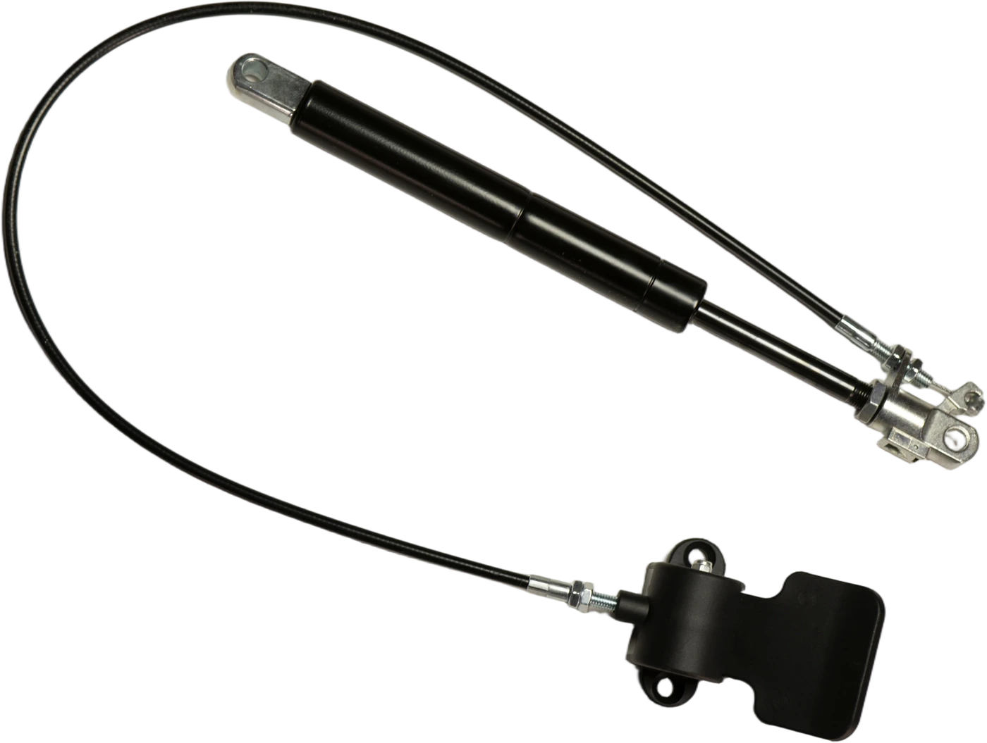
Original lockable gas spring with cable release and leverLOCKABLE GAS SPRING / CABLE RELEASE
Lockable Gas Springs product range illustration
Lockable Gas Springs

Adjust the position. Control when it moves.

Horizon supplies lockable gas springs for adjustable seating, backrests and guided table mechanisms. The spring can be quoted on its own or with a compatible release head, cable and lever. Operating the release allows adjustment; closing the valve provides the selected locking behavior.

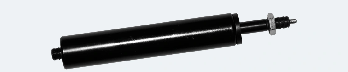
The photographed cable-release assembly shows the spring and control together. Extension force, holding load and release effort are separate specification items.

locking gas springsblockable gas springsrecliner gas springs
CONTROL & CONNECTION

The spring and control, supplied together.

Release-pin springs

A lockable gas spring for an existing compatible actuator. Pin location, movement and operating effort define the release interface.

Cable & lever controls

A spring and compatible release head with a cable-operated lever. Cable length, routing and lever position suit the surrounding mechanism.

Mounting connections

Threaded or pivoting end connections for the spring and release head. The selected locking behavior and load direction remain part of the assembly specification.

FULL PRODUCT VIEWComplete original product photograph with both ends visible
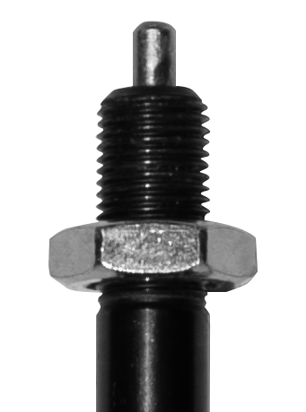
DETAIL / RELEASE PINOriginal photograph detail: release pin, thread and nut
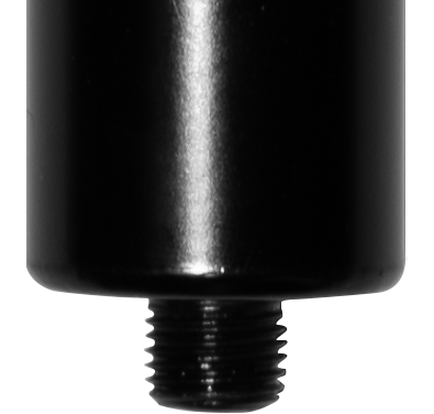
DETAIL / BODY ENDOriginal photograph detail of the cylinder-end thread

A release pin is not a complete control.

The close-up identifies the pin and mounting thread. A complete cable-release quotation also identifies the head, cable and lever; a spring-only quotation covers the component used with your existing compatible control.

Chair and seating applications
APPLICATIONS

Adjust and hold the chosen position.

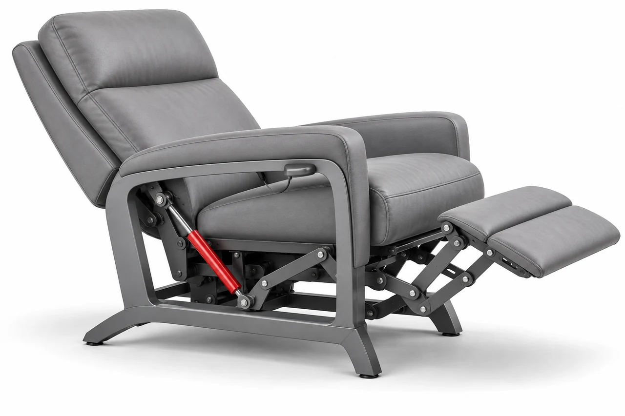
Complete recliner with a red locking gas spring connecting the fixed seat frame and adjustment linkageAPPLICATION / 01Recliners & adjustable backrestsExplore applications

Backrest position / Release control / Locking action

Uses & buying details

A release-controlled gas spring enables adjustment and holds the selected seating position. Match the original marking, elastic or rigid locking behavior, travel, connections and the complete cable or lever release arrangement.
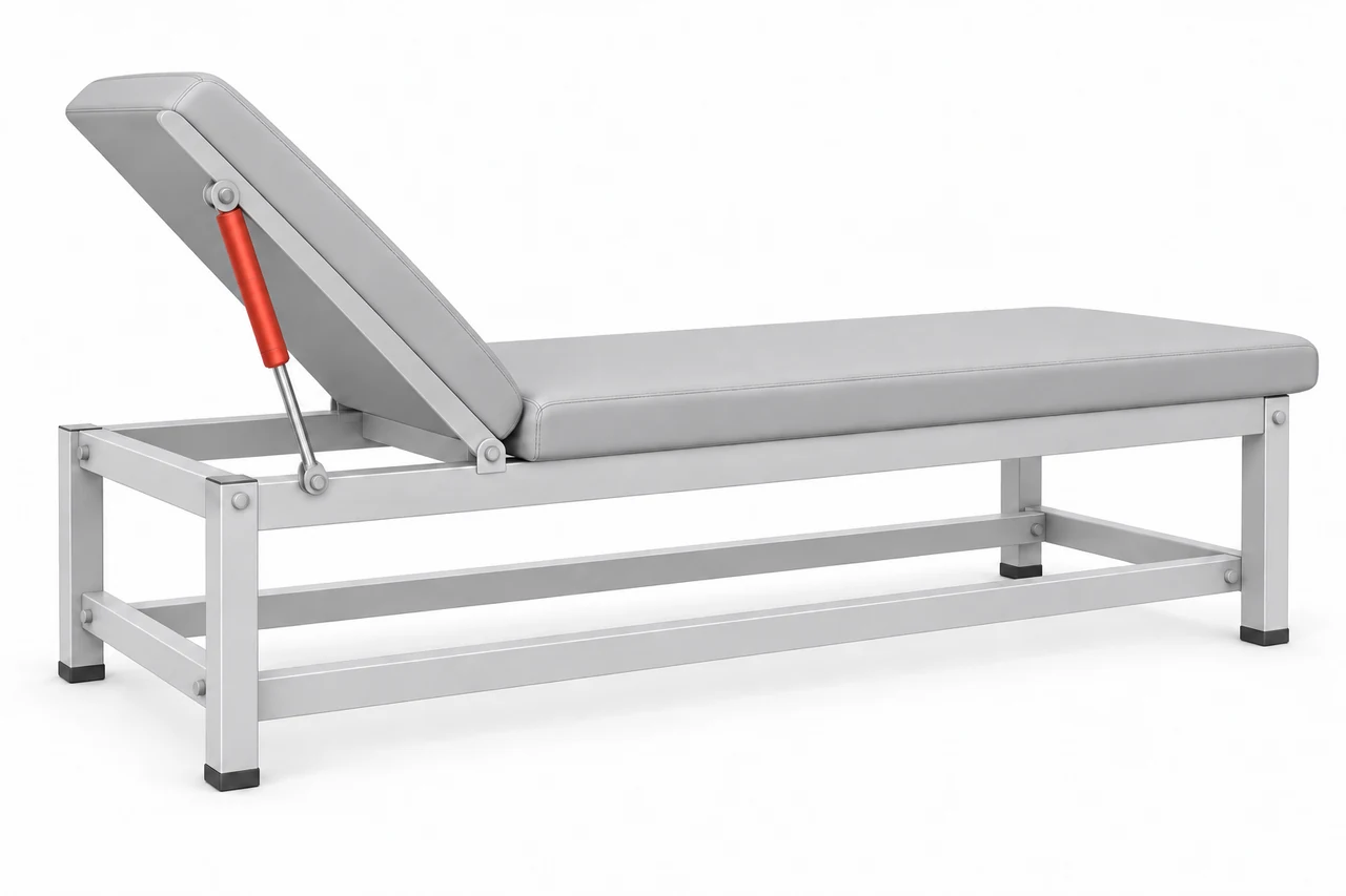
Complete treatment table with a locking support attached to the fixed side rail and moving backrest on the same sideAPPLICATION / 02Treatment-furniture backrestsExplore applications

Controlled backrest adjustment / Device specification

Uses & buying details

A locking support can position a hinged backrest between its fixed frame and moving section. Match the device model, release method, locking load and mounting details, and validate the component against the equipment specification.

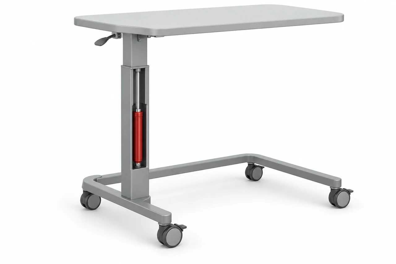
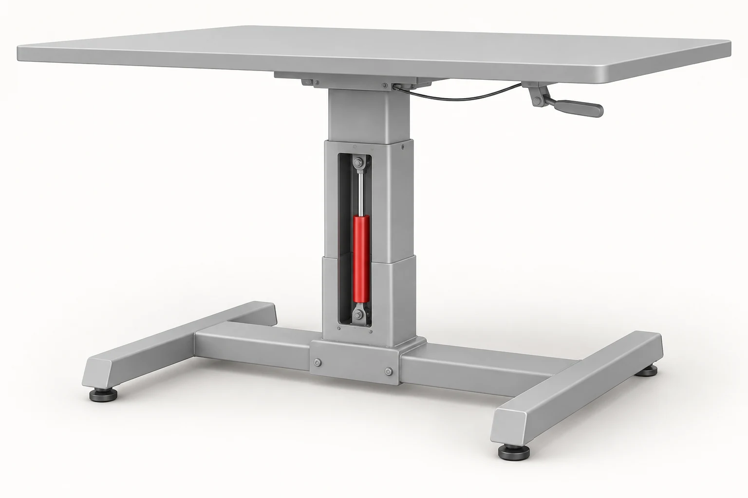
Complete height-adjustable worktable with an illustrative cutaway exposing the locking spring inside its guided columnAPPLICATION / 03Height-adjustable worktablesExplore applications

Guided column / Height adjustment / Release lever

Uses & buying details

A locking gas spring can work inside a guided height-adjustment column. Identify whether you need the complete column or its internal spring, then match travel, installed dimensions, connections and release operation. The model cutaway reveals the internal mechanism.

Complete overbed table with a guided vertical column and an illustrative opening showing its internal gas springAPPLICATION / 04Overbed tablesExplore applications

Table-height adjustment / Guided column assembly

Uses & buying details

A guided column provides controlled tabletop-height adjustment. Send the table or column reference, required travel, release method and assembly drawing. The model exposes the internal gas spring for clarity; the working column housing is enclosed.

MATCH AN EXISTING PART

Bring these details together.

  • Existing part marking
  • Extended and compressed length
  • Stroke and extension force
  • Locking behavior and required holding load
  • Release-pin or cable arrangement
  • End fittings and operating direction
  • Quantity
Gas spring mounting lengths: fully extended L1, fully compressed L2 and stroke S equals L1 minus L201 / MEASUREMENTExtended and compressed lengthMOUNTING CENTER TO MOUNTING CENTERFULLY EXTENDEDL1 / Extended lengthFULLY COMPRESSEDL2 / Compressed lengthSTROKES = L1 - L2Use the same mounting references in both positions.Schematic. The short rod neck and end-fitting geometry depend on the actual assembly.
FURTHER DETAILS

Connections and ordering.

Does the quotation include the release cable and lever?

A spring-only unit and a complete release assembly are different supply forms. For a complete assembly, the quotation identifies the compatible head, cable and lever as well as the spring and end connections.

Does extension force tell me how much the spring can hold?

No. Extension force, locking load and release operating force describe different functions. The holding requirement includes the load direction and the selected elastic or rigid locking behavior; these belong on the assembly specification.

Can I reuse the release control on my equipment?

The existing control can be assessed against the replacement spring interface. Pin location and travel, actuator effort, head engagement and return action all need to correspond. Photos of the head and a drawing help establish that connection.

CONTROL & ADJUSTMENT

The release interface is part of the product.

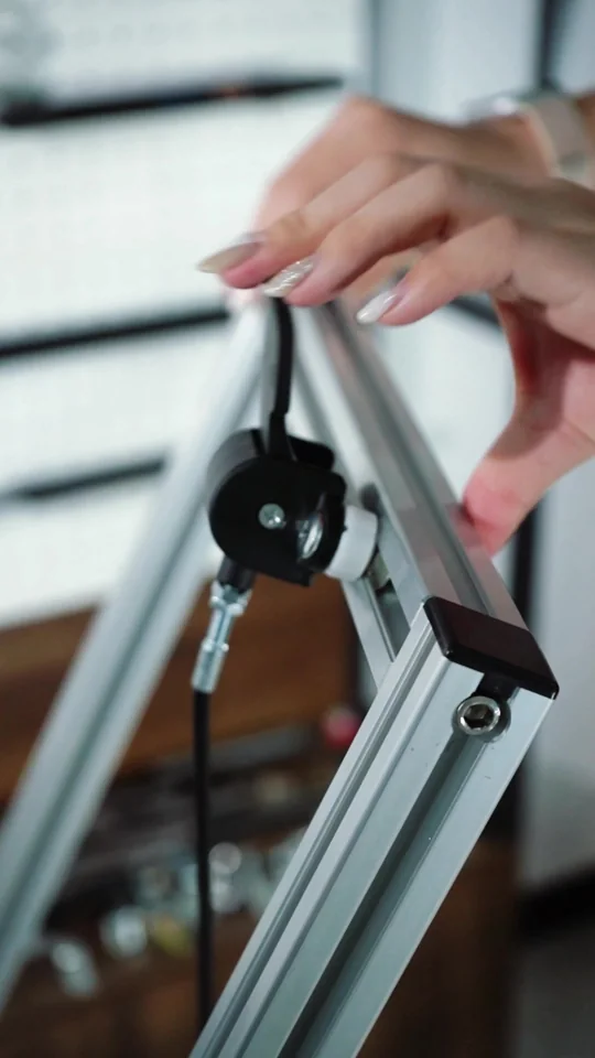
Close-up of the release control and its connection.
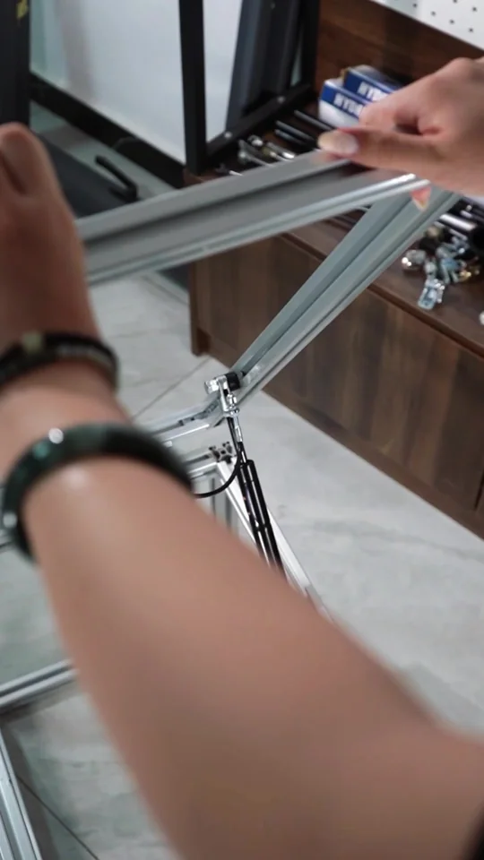
Manual adjustment of a frame with a release-controlled gas spring.

Original control and adjustment photographs. The approved assembly defines release travel, operating effort and holding capacity.

MATCHING DETAILS

Specify how it must hold.

RequirementWhat needs to be defined
Elastic lockingA compliant response under an added load. State how much movement is acceptable for the mechanism.
Rigid lockingResistance to movement in the specified direction up to the selected design's locking limit. It is not an unlimited load rating.
Compression / extension directionDefine which external load direction needs to be held. A design rigid in one direction need not behave identically in the other.
Three separate valuesExtension force, locking load and release operating force describe different functions. Keep them separate on the requirement.
Release-system compatibility checklist
InterfaceCheck before matching
Actuation pointRod-side or tube-side release, available space and direction of actuation.
Release travel and forceRequired pin movement and actuator effort; do not substitute the gas spring extension force.
Cable and headHead connection, cable route, available travel and clearance throughout adjustment.
Return to holdingThe release must return correctly and allow the intended holding behavior after operation.
End connectionsLength datums, threads, pivot sizes, permitted joint movement and assembly access.
Before approving a replacement

Check the complete configuration

Compare locking behavior, load direction, release method and operating conditions, as well as lengths and force.

Reusing a control

Match the existing cable or lever by head engagement, travel, operating force, routing and return action.