
APPLICATION GUIDE
Furniture Gas Springs
Find support and adjustment products for cabinets, beds, seating and gas-assisted furniture. Choose the furniture mechanism first, then match its gas spring and connections.
SUPPLY BY APPLICATION
Find the part of the product you work with.
| Application | Where it is used | Useful matching information |
|---|---|---|
| Cabinets & storage furniture | Lift-up cabinet fronts, chests and storage benches | Panel mechanism; strut marking; lengths; force; brackets |
| Storage beds & ottoman beds | Bed-base lifting and access to under-bed storage | Bed lift mechanism; strut count; original force; lengths; pin/eye sizes |
| Wall beds & folding furniture | Gas-assisted wall beds, foldaway panels and tables | Mechanism model; mounted orientation; exact strut specification |
| Recliners & adjustable seating | Backrest, headrest and leg-rest adjustment | Locking function; release arrangement; travel; mounting ends |
| Tables & work surfaces | Gas-assisted side tables, lift-top tables and work surfaces | Required motion; locking function; column or strut dimensions |
| Monitor arms & supports | Gas-assisted display arms and adjustable supports | Arm assembly; counterbalance requirement; dimensions; mounting details |
MATCHING NOTES
Start with the furniture mechanism.
An overhead cabinet flap, a storage-bed base, a wall bed and a reclining backrest need different motion and mounting arrangements. Note the existing mechanism and the number of gas springs used. Furniture fitted with electric or hydraulic drives belongs to a different component category.
Published application & size references
| Application / reference | Published identification | Published dimensions / force | Quotation / source |
|---|---|---|---|
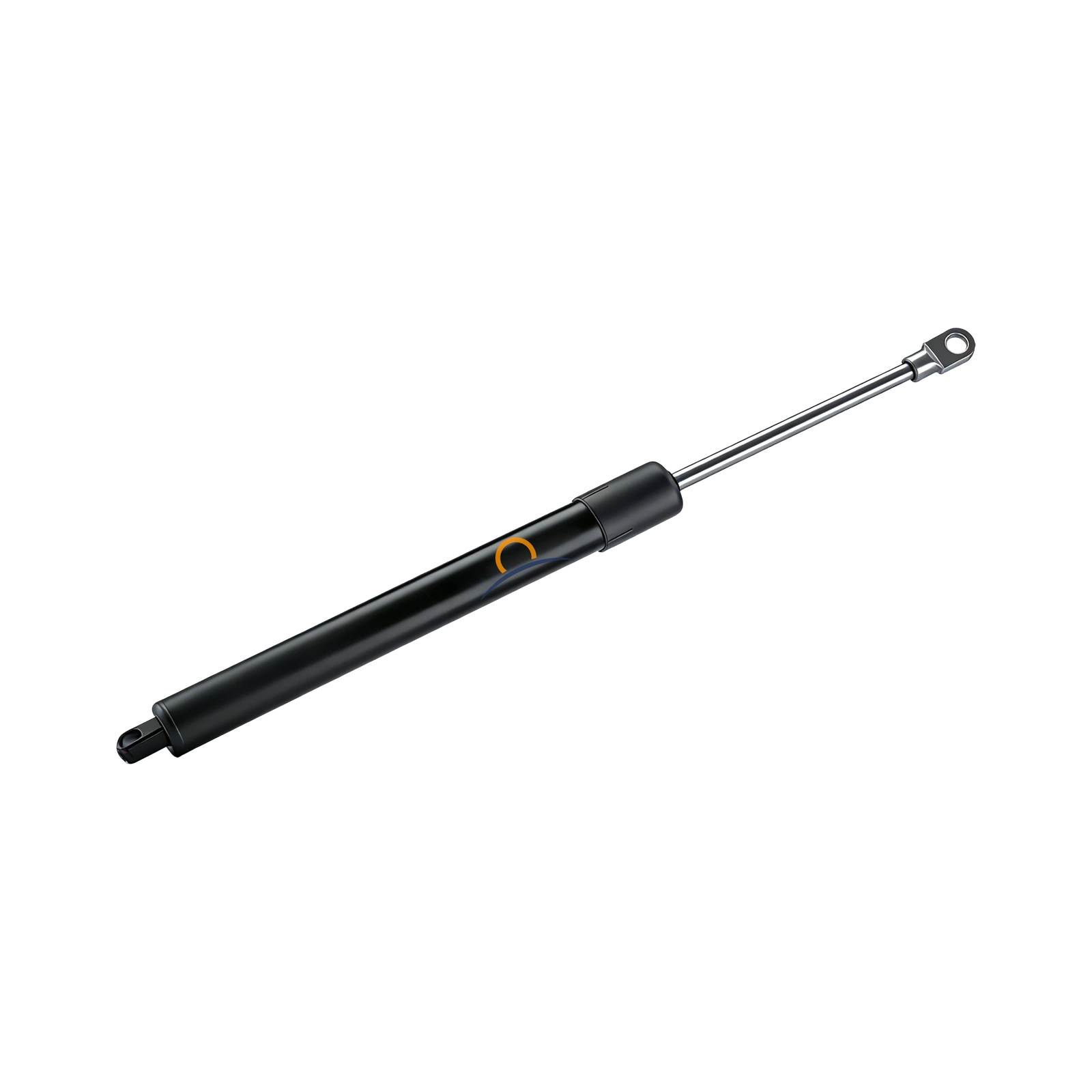
| Cabinet flap reference - 50 NReference for the source mounting arrangement and an 18 mm MDF/chipboard flap. | SUSPA S01625512— | Extended: 244 ±2 mm / 9.61 in (nominal) Max. stroke: 85 mm / 3.35 in Force: 50 N / ≈11.2 lbf Source mounting example: 600 mm wide × 351–400 mm high × 18 mm thick panel; 2.5–2.8 kg; 2 gas spring(s) per flap. Applies only to the source mounting geometry and panel construction. Source attachment system C7 / C9 | Quote reference Source ↗Published reference |
| Cabinet flap reference - 80 NReference for the source mounting arrangement and an 18 mm MDF/chipboard flap. | SUSPA S01625513— | Extended: 244 ±2 mm / 9.61 in (nominal) Max. stroke: 85 mm / 3.35 in Force: 80 N / ≈18.0 lbf Source mounting example: 450 mm wide × 300–350 mm high × 18 mm thick panel; 1.6–1.8 kg; 1 gas spring(s) per flap. Applies only to the source mounting geometry and panel construction. Source attachment system C7 / C9 | Quote reference Source ↗Published reference |
| Cabinet flap reference - 100 NReference for the source mounting arrangement and an 18 mm MDF/chipboard flap. | SUSPA S01625514— | Extended: 244 ±2 mm / 9.61 in (nominal) Max. stroke: 85 mm / 3.35 in Force: 100 N / ≈22.5 lbf Source mounting example: 600 mm wide × 501–550 mm high × 18 mm thick panel; 3.5–3.9 kg; 2 gas spring(s) per flap. Applies only to the source mounting geometry and panel construction. Source attachment system C7 / C9 | Quote reference Source ↗Published reference |
| Cabinet flap reference - 120 NReference for the source mounting arrangement and an 18 mm MDF/chipboard flap. | SUSPA S01625515— | Extended: 244 ±2 mm / 9.61 in (nominal) Max. stroke: 85 mm / 3.35 in Force: 120 N / ≈27.0 lbf Source mounting example: 600 mm wide × 551–600 mm high × 18 mm thick panel; 3.9–4.2 kg; 2 gas spring(s) per flap. Applies only to the source mounting geometry and panel construction. Source attachment system C7 / C9 | Quote reference Source ↗Published reference |
Published references identify a matching request; they are not Horizon stock codes or an authorized-distributor claim. The quotation confirms the actual supplied assembly. Brand names are used for identification.
Explore all reference records →FOR Furniture manufacturers / Furniture-hardware distributors
A clear parts list makes a clearer quote.
- Furniture or mechanism type
- Existing strut or mechanism model
- Lengths and stroke
- Force marking
- Both end connections
- Quantity
PRODUCT CONNECTIONS
Continue with the right product range.
YOUR NEXT STEP
Have a part number, dimensions or a parts list?
Send the reference and quantity for each item. We will match the requirement and prepare a quotation for your order.