
Read the part. Measure the fit.
A practical guide to gas spring dimensions, force markings, connections and working principles. Keep the complete assembly in view when comparing a replacement.
Use the same reference points.
The fully extended assembly measured between the specified mounting references.
The fully compressed assembly measured between those same references.
The change in length: L1 minus L2. Do not confuse stroke with the total visible rod length.
For eyelets or ball sockets, include the specified mounting centers. Threaded bare ends use the drawing datum.
Support the lid or equipment independently before inspecting a fitted gas spring. Do not force a pressurized gas spring closed by improvised means to obtain a measurement.
Keep the number and its unit together.
A marking such as 300 N describes force. It does not mean the gas spring can safely support a 30 kg lid in every installation.
The required force depends on the panel weight, center of gravity, mounting geometry, opening position and number of supports. For a replacement, record the original force marking and the complete part reference.
For locking gas springs, extension force and locking load are different specifications.
| Convert | Relationship |
|---|---|
| Length | 1 in = 25.4 mm |
| Force | 1 lbf ≈ 4.44822 N |
| Example | 300 N ≈ 67.4 lbf |
Conversions do not establish a product force rating or an approved mounting arrangement.
Identify both ends separately.
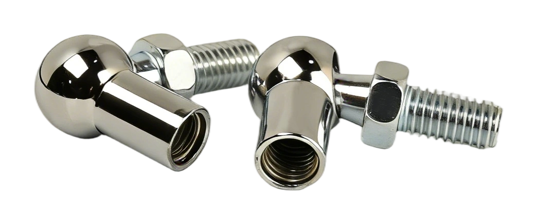
Ball socket & stud
Record ball diameter, socket thread, stud thread and retaining arrangement.
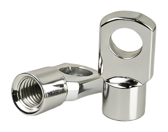
Eyelet connection
Record bore diameter, width, thread and mounting-center position.
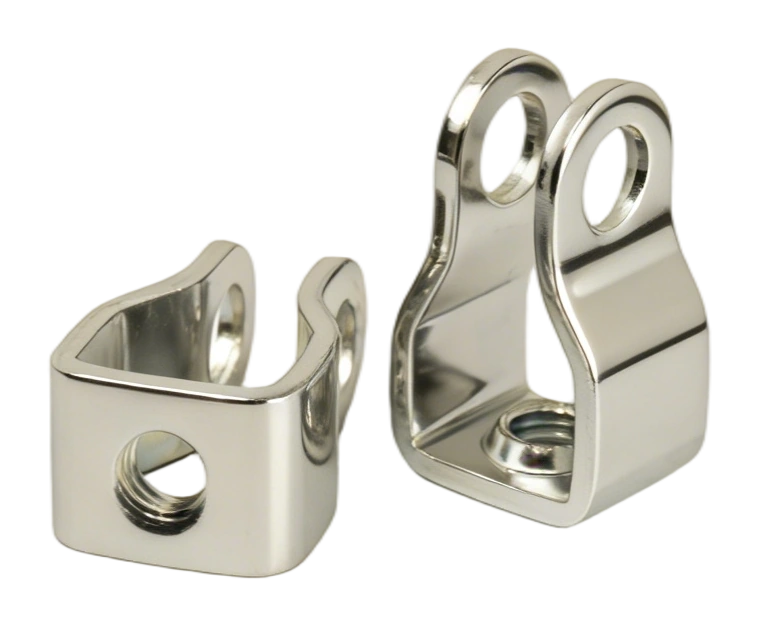
Clevis connection
Record pin diameter, inside width, thread and center length.
Understand the component you are matching.
Compression gas spring
Pressurized nitrogen provides outward force. The rod moves through a sealing and guide assembly; the piston and flow path influence motion. Oil supports lubrication and, in suitable designs, end-position cushioning.
Locking and traction designs
A lockable gas spring adds a controlled valve function. A traction gas spring pulls toward retraction. These functions cannot be identified from a similar-looking outer tube alone.
Technical reading: SUSPA gas spring principlesConnection terminology
Have a part number, dimensions or a parts list?
Send the reference and quantity for each item. We will match the requirement and prepare a quotation for your order.