
Complete eyelet assemblies
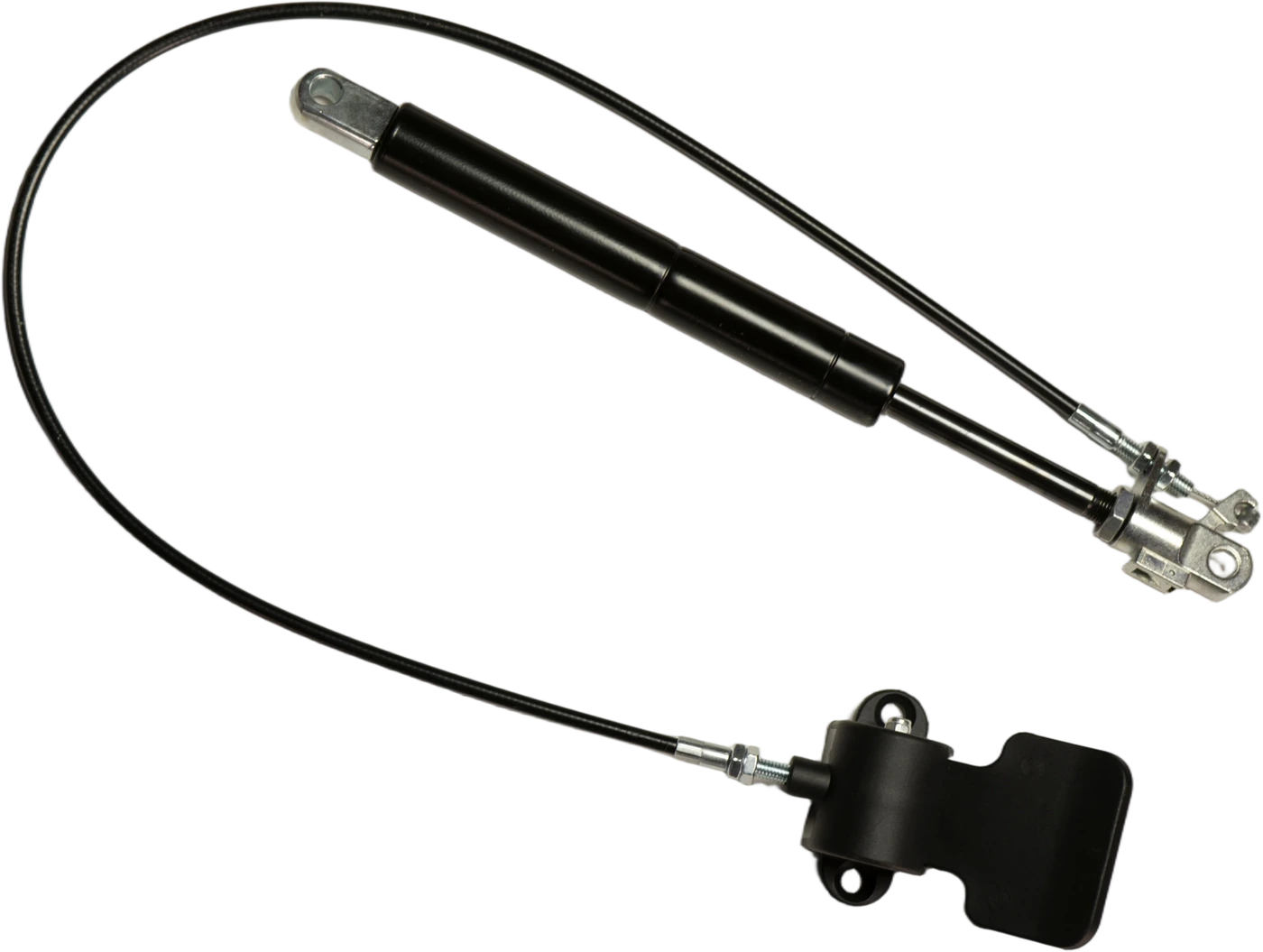
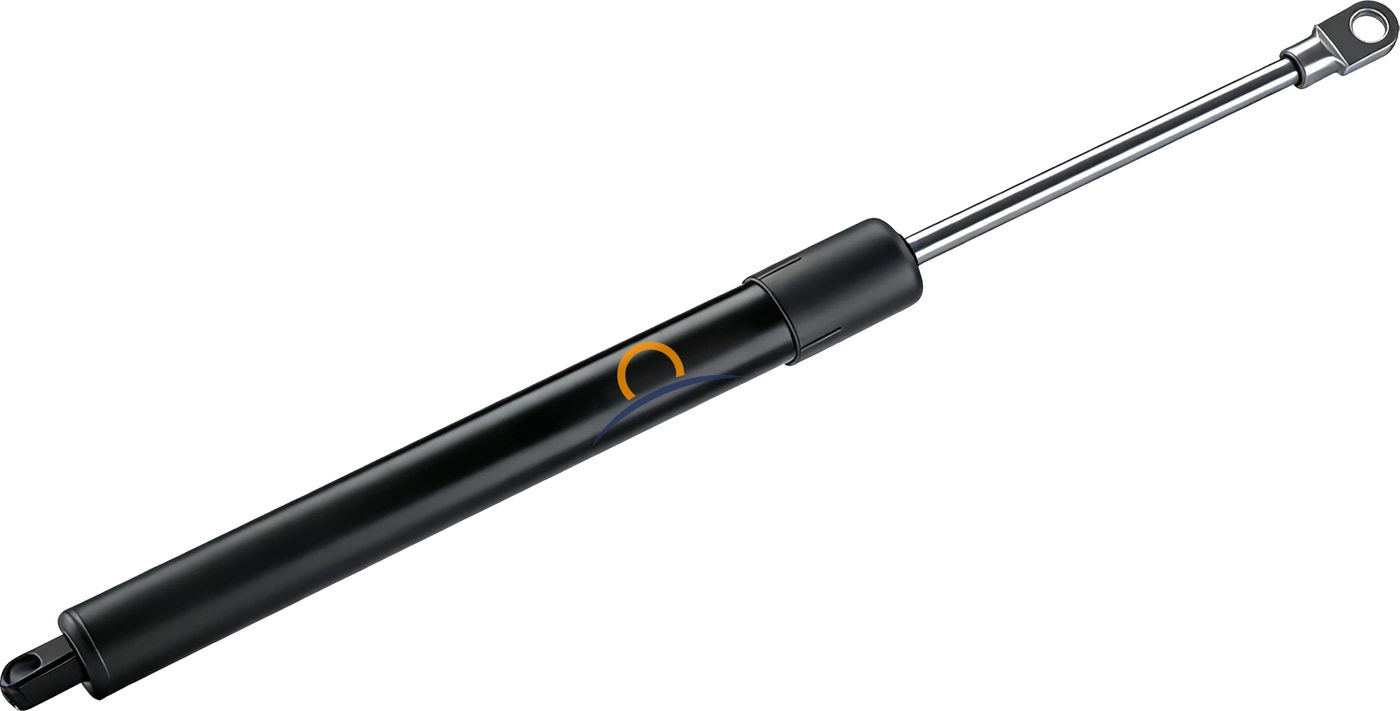
Gas springs supplied with eyelet ends for pin or pivot-bracket mounting. The hole size, eyelet width and mounting-center lengths describe the complete assembly.
Explore connection options →Lift supports for lids, hatches and covers.
Horizon supplies compression gas springs as complete lift supports with selected end fittings, or as threaded-end units for your own mounting hardware. Used on vehicle hoods, furniture lids and equipment covers, these gas struts push outward to assist opening and support the moving panel.
Choose the required assembly form below. Length, stroke, force and both connections define the supplied configuration.
Order the spring with its selected mounting ends, a threaded-end unit, or connection hardware for an existing assembly. Vehicle and furniture reference pages provide published application and dimension records to help identify the required version.
Gas springs supplied with eyelet ends for pin or pivot-bracket mounting. The hole size, eyelet width and mounting-center lengths describe the complete assembly.
Explore connection options →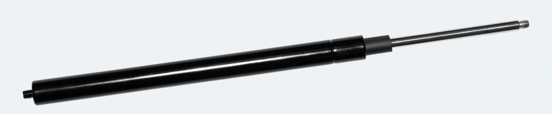
Gas springs with threaded rod and tube ends for separate fittings. Threads and shoulder datums are defined before adding ball sockets, eyelets or clevis ends.
Compare end fittings →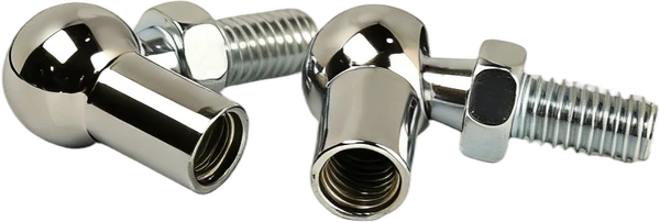
Ball sockets, ball studs, eyelets, clevis ends and brackets can be quoted with the spring or as connection hardware. Rod-end and tube-end connections are specified individually.
See fittings and brackets →| Specification | Definition |
|---|---|
| Extended length L1 | Distance between the specified mounting references when fully extended, with the selected fittings included. |
| Compressed length L2 | Distance between the same mounting references at the specified compressed position. |
| Stroke S | L1 − L2, using unchanged end fittings and measurement references. |
| Tube / rod diameter | Two separate diameters, stated in that order. They do not determine the selected force on their own. |
| Force | A force value in N with a defined measuring position and conditions. Force is not the supported panel weight. |
| Connections | Rod-end and tube-end fittings defined separately, including their thread or pivot dimensions. |
Ball-joint lengths use ball centers; eyelet lengths use hole centers. Threaded-end drawings state their own end or shoulder reference. Both measuring positions use the same datums.
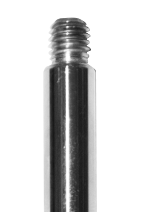
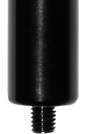
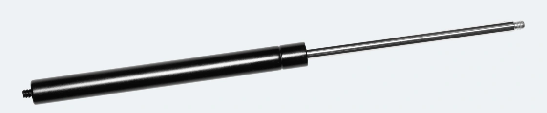
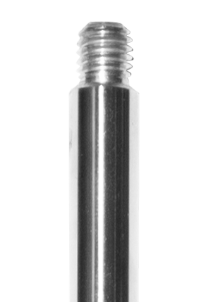
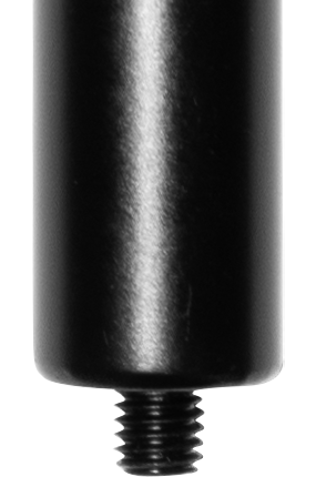
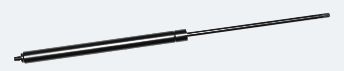
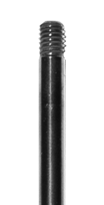
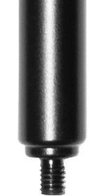
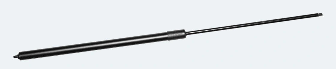
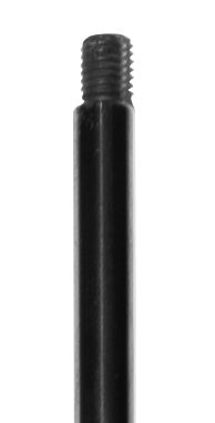
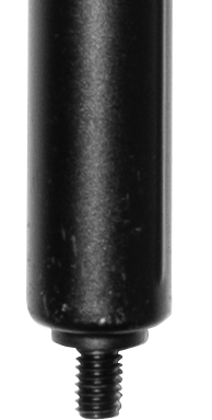
Threaded ends, slender rods, cylinder profiles and connection choices. Each photograph retains the original product proportions.
 APPLICATION / 01Automotive Lift SupportsExplore applications ↗
Find gas springs for hoods, liftgates, trunk lids and rear glass. Start with the original marking and the vehicle information to identify a replacement requirement.
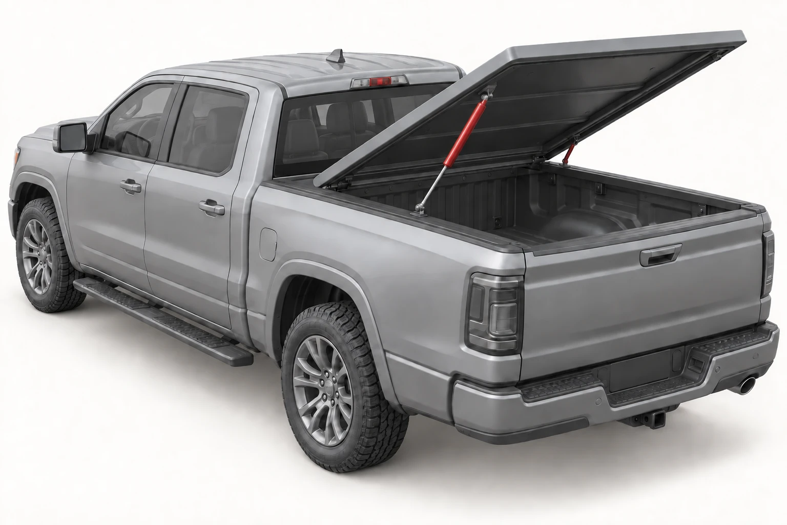 APPLICATION / 02Pickup, RV & Trailer Gas StrutsExplore applications ↗
Gas springs for truck-cap windows, tonneau covers, RV compartments and camper furniture. Identify the fitted accessory as well as the vehicle.
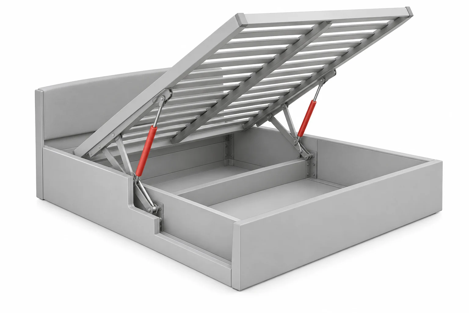 APPLICATION / 03Furniture Gas SpringsExplore applications ↗
Find support and adjustment products for cabinets, beds, seating and gas-assisted furniture. Choose the furniture mechanism first, then match its gas spring and connections.
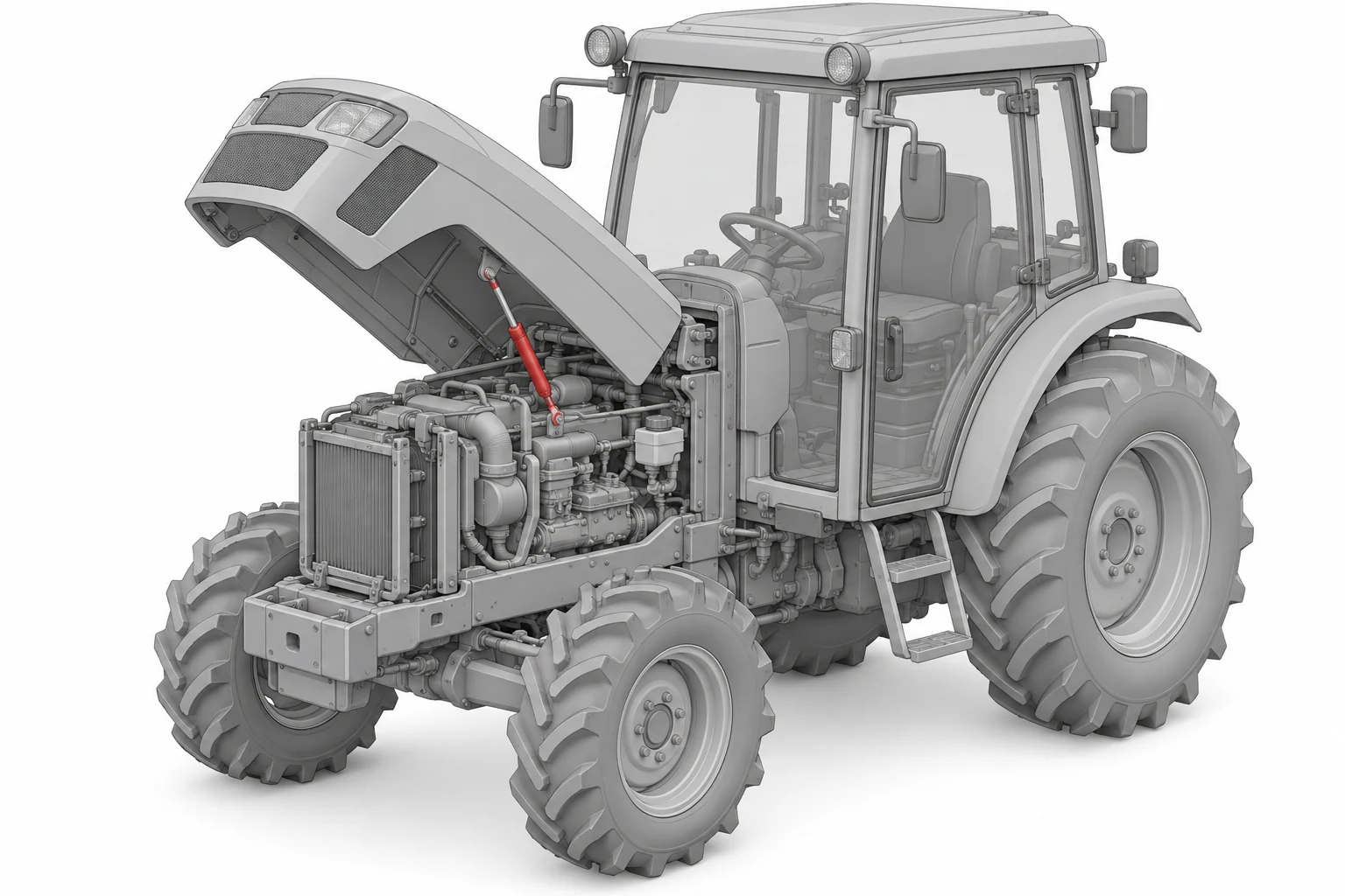 APPLICATION / 04Construction & Agricultural EquipmentExplore applications ↗
Gas springs for machine hoods, cab access and service compartments. Identify the equipment and the exact access panel before matching the support.
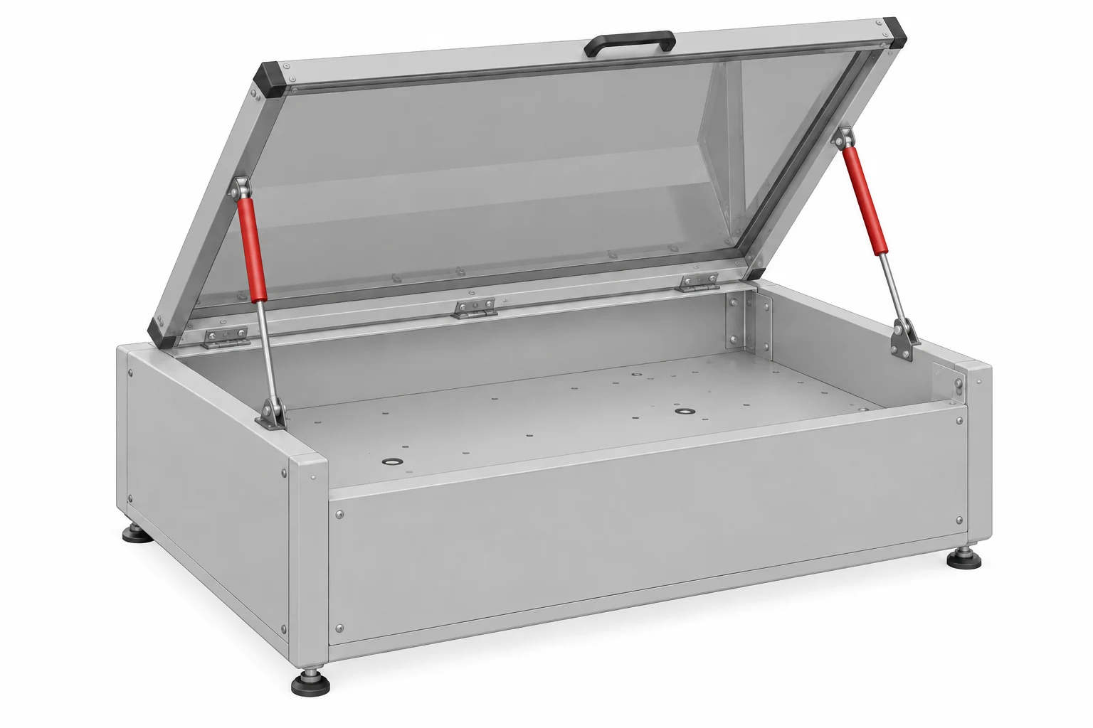 APPLICATION / 05Industrial & Commercial EquipmentExplore applications ↗
Gas springs for equipment covers, guards and access panels, with locking options for adjustable supports. Match the existing part or provide a drawing with mounting details.
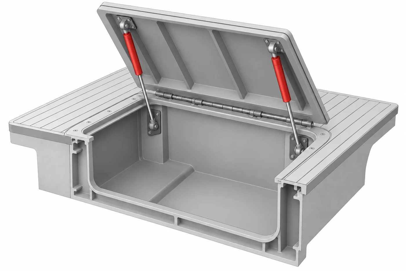 APPLICATION / 06Marine & Outdoor Gas SpringsExplore applications ↗
Support hatch, locker and access-panel applications with a material and fitting specification suited to the exposure. Match the complete assembly, including mounting hardware.
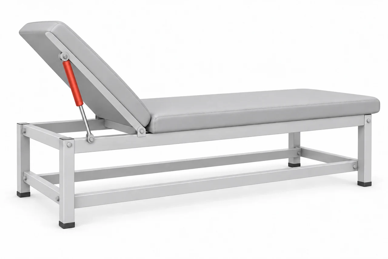 APPLICATION / 07Medical & Rehabilitation EquipmentExplore applications ↗
Gas springs for assisted adjustment in treatment furniture, rehabilitation seating and equipment access. Match the product to the device's specified motion and validation requirements.
Both forms are part of the compression range. A complete support includes the selected mounting ends; a threaded-end unit is defined at its own thread or shoulder datums. The quotation identifies which form is included.
Yes. Similar-looking gas struts can use different forces, stroke lengths or mounting ends. We quote these as separate configurations, including the required rod-end and tube-end fittings, rather than treating appearance as a part specification.
Yes. Send your parts list with a quantity per line. Existing references and drawing-based specifications can be reviewed in the same inquiry; each quoted line identifies its selected assembly and packing requirement.
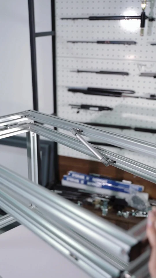
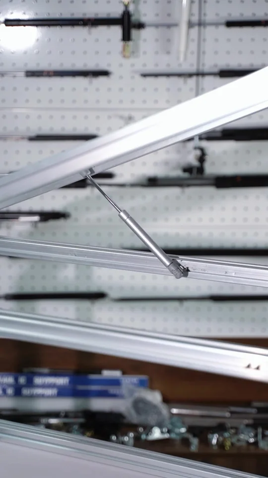
Two positions of a physical lifting-frame demonstration. They show the mounting relationship; they are not a load rating or an installation drawing.
| Dimension | Record it this way |
|---|---|
| Extended / retracted length | Use identical mounting references at both positions; identify whether the end fittings are included. |
| Stroke | Travel between the specified end positions. With unchanged fittings and datums: stroke = extended length - retracted length. |
| Tube and rod diameters | Record both independently. Neither the thread size nor a similar outer tube identifies the force. |
| Threaded-end datums | A bare-thread or shoulder datum can differ from a ball-center datum. Mark the actual reference on the drawing. |
State the force value in N together with the measurement position, direction and conditions. An F1 marking does not describe the entire stroke.
Compression reduces available gas volume in conventional compression designs. Seal friction also separates the compression and extension force curves.
Check opening effort, closing effort, travel speed, latch load and clearances across the full movement, including the intended temperatures.
Keep both lengths, stroke, force, damping, both end fittings, materials and the drawing revision together. Matching only force is insufficient.
Confirm a compressed dimension from the drawing or an appropriate controlled check. Do not force a resistant unit closed simply to measure it.