
Skip to content
GAS SPRINGS & LIFT SUPPORTS · B2B SUPPLY
sales@horizongasspring.com
Language / EN

Read in your language

Automatic translation by Google. Opens in a new tab.

English Original website

Quotes & PDF catalog: original English website.

PRODUCT RANGE

Traction Gas Springs

Pulling force for return and closing functions.

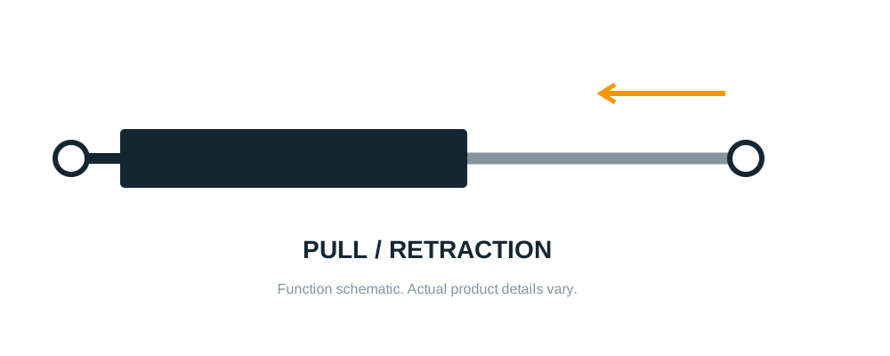
Traction gas spring force acts inwardMOTION DIRECTIONTraction / pulling assistanceFUNCTION SCHEMATICPULL INForce acts toward retraction.The required motion is specified independently of the exterior appearance.
Traction Gas Springs product range illustration
Traction Gas Springs

Pulling force for return and closing functions.

Horizon supplies traction gas springs, also called tension or pull-type gas springs, for mechanisms that need an inward return force. Threaded-end units and supports with selected end connections are quoted by their working travel, mounting lengths and pull-force requirement.

The pull force, damping requirement and any separate holding function are defined individually for the mechanism.

tension gas springspull-type gas springsgas traction springs
MOTION DIRECTION

Pulling assistance, clearly identified.

Traction gas spring force acts inwardMOTION DIRECTIONTraction / pulling assistanceFUNCTION SCHEMATICPULL INForce acts toward retraction.The required motion is specified independently of the exterior appearance.
Compression gas spring force acts outwardMOTION DIRECTIONCompression / lifting assistanceFUNCTION SCHEMATICPUSH OUTForce acts toward extension.The required motion is specified independently of the exterior appearance.

A traction gas spring is a different design from a compression strut. Turning a compression gas spring around does not reverse its force.

APPLICATIONS

Find the relevant buying guide.

MATCH AN EXISTING PART

Bring these details together.

  • Existing part or drawing
  • Retracted and extended mounting length
  • Stroke
  • Pull force and measurement position
  • End fittings
  • Quantity
Gas spring mounting lengths: fully extended L1, fully compressed L2 and stroke S equals L1 minus L201 / MEASUREMENTExtended and compressed lengthMOUNTING CENTER TO MOUNTING CENTERFULLY EXTENDEDL1 / Extended lengthFULLY COMPRESSEDL2 / Compressed lengthSTROKES = L1 - L2Use the same mounting references in both positions.Schematic. The short rod neck and end-fitting geometry depend on the actual assembly.
FURTHER DETAILS

Connections and ordering.

Is a traction gas spring a compressed version of a lift support?

No. A traction spring is designed to exert an inward pulling force. A compression lift support pushes outward even when it is compressed; the same exterior shape or mounting length does not make the two interchangeable.

Can you include the end connections?

Yes. A traction spring can be quoted with selected end connections or as a threaded-end component. The rod and body ends are defined separately, including thread or pivot dimensions and the movement required at each joint.

Does pulling force also control the closing speed?

Pulling assistance and speed control are separate requirements. A quote for a return spring identifies the pull force and travel; any required damping or holding function needs its own specification for the complete mechanism.

MATCHING DETAILS

Pulling, damping and locking are separate decisions.

Required resultMatching implication
Pull toward retractionIdentify a traction / tension design. A compression spring of similar size acts in the opposite direction.
Control closing speedSpecify damping separately. Pulling force by itself does not define a controlled speed profile.
Hold a positionA return-force requirement is not a positive-locking requirement. State any separate latch or holding function.
Fit the mechanismCheck both installed lengths, travel, end fittings and clearances at the start, middle and end positions.
Installation and movement checks

Model-specific orientation

Use the instructions for the selected traction design. Do not automatically apply the rod-down rule of a conventional compression gas spring.

Aligned joints

Avoid bending, twisting or side loading the rod. Connections must move freely throughout the intended travel.

Travel limits

Keep the mechanism within the specified working stroke. Use suitable travel stops and do not overextend the unit.

Supported handling

Support the mechanism independently for installation or service. Protect the polished rod from clamping, impact and scratches.